Categories
electronics remote temperature sensor sensors

Stephenson screen

A first attempt at a Stephenson screen for the outdoor temperature sensor. It is just a section of PVC pipe with a cowl on it to keep the rain (mostly) out, with a thinner pipe suspended on the inside, with the sensor suspended within that, near the lower end. The idea being that the inner pipe won’t see direct sunlight, and air between the pipes heated by the sun on the outer pipe will vent up and out, drawing fresh air in the bottom.

I’m currently testing it in parallel with the sensor at the back of the house (which gets badly sun-affected in the mid morning).

image

Categories
electronics sensors Uncategorized

Finalized currentcost interface for rPi

Having breadboarded it a couple of days ago, I’ve now finalized the serial interface between the Raspberry Pi and the Currentcost cc128, using some stripboard, dual header socket, CD4049, and a couple of bits of wire. Pretty straightforward; I removed a couple of pins from the header socket so I didn’t have to bridge from the outside of the socket back into the middle of the board, and made sure that all unused gates have their outputs floating and their inputs tied to something (in one case I’ve actually fed the input of a spare gate from the output fed to the rPi RX line; yes it will slightly increase the current consumption (as I’ve got an extra gate switching instead of staying static), but the effect will be tiny and it was easier than cutting the trace and fixing it all up with wires). The stripboard could have had the outer two rows of holes trimmed off but it doesn’t interfere with anything so I didn’t bother. The LEGO case has been improved now that I don’t have wires out the side (and has a transparent block near the LEDs on the rPi – works very well).

Parts
Note the two missing pins in the header. There's a missing cut on the stripboard, and one cut in the wrong place.
Top view
Top view
Bottom view
Bottom view, with missing cuts added and wrong cut bridged; yes my soldering is awful.
In situ
With cc128 meter and rj45 connection
Boxed and ready to go


Machine is now under the bed driving the (USB) bedroom speakers using shairport and feeding power data to my main server over MQTT.

Categories
electronics remote temperature sensor sensors

Finishing phase 1 of the remote temperature sensor

So, as seems to be the way with blogs, I never did get around to documenting the next stages of the project. A bit of a catchup is clearly in order.

Currently the transmitter is hanging under the eaves on the north side of the house where it is reasonably well hidden from the sun (given I am in the southern hemisphere that sounds all wrong, but there is a tree in the right place and no sensible place on the south side of the house), and in easy reach of a power outlet which happens to be on the outside of the house there. This is sub-optimal, as the temperature it measures is clearly heavily influenced by the house itself (on still nights, it doesn’t get anywhere near as cold as it should, but on windy nights it roughly matches the output of the nearest official weather station). I do have a LiPo battery and a “Lipo Rider” board (the 0.9 version I think), but I don’t currently have the solar panel to keep the battery charged, and I haven’t built something approximating a Stevenson screen yet (although I am planning something much simpler with a couple of concentric PVC pipes).

The temp-sens-bits zip file referenced below actually includes the rf receiver circuit and layout as well; it is extremely simple, since I just use the receiver sub-board to drive the receive pin on a cheap 5v USB to rs232 breakout, with a buffer in between to drive enough current to keep the usb chip happy.

schematic for the remote temperature sensor rf receiver circuit
RF receiver schematic

The receiver doesn’t actually have 20 pins, (it has 4 at each end) but I needed it to be the right length to generate the layout correctly:

veroboard layout for the remote temperature sensor receiver
veroboard layout for the receiver

The 7-pin header is where the usb-serial widget goes (which was from Little Bird but I don’t think is sold by them any more), and the chip is a 4049 cmos hex inverter buffering the output of the receiver.

Firmware is pretty simple; I’ve use the Arduino programming environment with the NewSoftwareSerial, OneWire and DallasTemperature libraries. The source is in the temp-sens-bits zip file (warning: it is ugly and includes loads of commented-out debugging). The code on the server which processes the output will be the subject of a later post.

Categories
electronics remote temperature sensor sensors

Remote temperature monitor project – transmitter complete!

After learning how to use VeeCAD and TinyCAD, I’ve got a layout, and I start the rather tedious process of cutting tracks (with a hand-held drillbit – I don’t happen to own a drill press… yet), then soldering the jumper wires, then the passive components, then measuring resistance here there and everywhere to make sure I don’t have bridged joints etc before finally attaching the chip and transmitter module – and I end up with this:

Component side view of the finished board

Solder-side view of the board
my not-very-good soldering...

And now I need to test it in the outside world, so a 9V battery and 78L05 regulator later, plus an “enclosure”:

Temperature monitor in a temporary outdoor "enclosure" (lunchbox)
Yum! Oh wait...

I stick it in the fork of a tree in the back garden, and go back inside to try it out.

First indications are not particularly encouraging – while my “U U U U U U U U ” sync header seems to be working reasonably well, only about every 5th message is actually making it back to the receiver uncorrupted. Still, I hack together a very quick python script to pull out the data (which does have a checksum), and then I move the receiver (still on breadboard) from the workstation to the server at the other side of the office.

And then discover something amazing – the noise has all vanished, and all my messages are coming through clean and clear with no garbage between transmissions! Something on my desk must be producing a reasonable amount of noise around 315MHz – my guess is it would have to be one of the monitors. Whatever, my noise problems are now basically solved, and the server is getting data!

Categories
electronics remote temperature sensor sensors

From breadboard to PCB – but how?

So I’ve got my project on breadboard (and a hand-drawn schematic on a scrap of paper) and now I want to put it on permanent substrate of some sort. So what are the options?

  • Hand designed, hand drawn PCB. However it has been 20 years since I’ve done this, and I don’t really want to get into the whole chemical etching thing just now.
  • Draw it on a computer (what software?), print it, get a UV lamp and some photoresist board, expose it – and chemical etch it.
  • Draw it on a computer, print it reversed on a laser printer, and use a sandwich maker or iron to transfer the toner to bare copperclad – and chemical etch it.

At this stage, none of these are appealing for a project of this size, especially as I’m not sure if I’ve been (re)bitten enough by the electronics bug to make the investment worthwhile. So I take the easy way out, and go for veroboard.

And then I discover how painful it is trying to produce a reasonably compact layout by hand on graphpaper, and decide that There Must Be a Better Way.

Much googling later (and a bit of playing around with gEDA – which I may revisit if I do get into designing custom boards), I end up trying out VeeCAD. I don’t like the fact that it is closed-source and windows-only, but it does run on wine and has a free edition. Still makes me feel dirty.

I then realize that to make it work for me, I’m going to have to find something to do schematic capture, and VeeCAD seems to work best with TinyCAD. Which is also windows-only, but is at least open-source and runs on wine.

So I capture a circuit diagram:

Circuit Schematic for remote temperature monitor
Circuit Schematic

And generate a verboard layout:

A verboard layout for the remote temperature sensor
Veroboard layout

The free version of VeeCAD doesn’t put component names or values on the veroboard layout, and I’ve obscured it slightly by mounting 2 of the resistors vertically (or nearly so), but you can probably figure out which bit is which if for some reason you are mad enough to want to reproduce it for yourself. Here is a zip file with the actual VeeCAD and TinyCAD data files: temp-sens-bits. I’m sure the veroboard layout could be done much better by someone who actually knew what they were doing 🙂

Categories
electronics remote temperature sensor sensors

Remote temperature monitor project – breadboard prototype

So now I have all the bits (microcontroller chip, usb- 5v serial module to program it with, transmitter, receiver, another cheap usb-5v serial to build the receiver around, a DS18S20 and a bunch of passive components). I also have a double breadboard, and the circuit diagram for the arduino boards so I know roughly how to put one together (basing it on the stripped down “Pro” model, in 5v 16MHz form). This means I can build it with the reset pin correctly tied to the usb-serial widget to auto-reset on sketch download etc.

At first it all goes well; I get my bare ‘168 up and running with an LED attached, and download the blink code to it, and it blinks nicely. I plug a couple of DS18S20 units in and get temperature readings from them which look sane. I learn how to use the software serial library to drive a second serial bus (so I can use the hardware one for debugging and sketch downloading at the same time).

However, when I try using the wireless devices, I can’t get anything out of the receiver. Zip. Zilch. Nada.

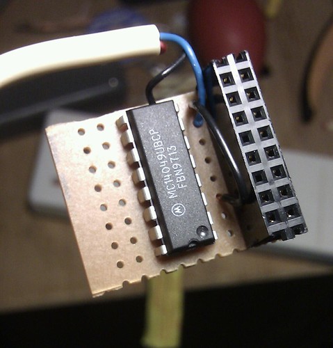
Much headscratching ensues. I’m just about to give in and send the units back to littlebird (which would have been awkward since this was over the christmas break), when a final google search turned up a suggestion that the exact module I’m using may not be able to sink enough current to drive the microcontroller input pin. A trip to Aztronics to get a cmos 4049 hex inverter, and I start getting output!

Trouble is, its mostly rubbish. The receiver appears to be extremely noisy, especially if the transmitter isn’t actively transmitting. In addition, sometimes I appear to be losing a bit or so at the start of transmissions, leading to complete gibberish as the receiver gets out of sync with the transmitter. After fiddling around with different bit patterns, I discover that putting the sequence “U U U U U U U U ” at the start of my transmission almost always results in the receiver getting synced up OK before the actual message starts arriving.

I also discover that having both the transmitter and receiver on the same breadboard means I need to not have any antenna wires, otherwise I don’t get anything but noise – I’m guessing the transmitter is completely overwhelming the receiver at this point.

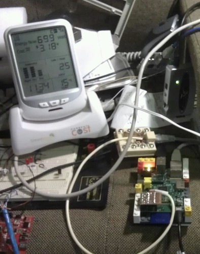
But at least the breadboard prototype seems to be working.

Categories
electronics remote temperature sensor sensors

Remote temperature monitor project – inspiration.

So having got fed up with not knowing what the temperature in my office is, or how hot it is outside my house rather than several km away where the Bureau of Meteorology site is, and having heard about the neat little DS18S20 digital temperature sensors, built one of the “k145” kits from kitsrus.com, thinking that 4 sensors would be enough, and I’d hang one outside somewhere. The “1-Wire” bus these devices use can go quite a long way, so it seemed like a simple thing.

Then I started reading a bit about weather monitoring stuff, and I realized I was going to have to think about what might happen in the event of a lightning strike.

First I looked at isolating the 1-Wire bus back to the existing k145, but that turns out to be distinctly non-trivial; the application note on how to isolate a 1-wire bus involves a transformer, and actually results in the bus no longer being a 1-wire at the microcontroller end but having separate transmit and receive paths, which means it wouldn’t work on the existing widget.

The I bought an Arduino work-alike (an ET-Easy168 – more or less a clone of the older Nano with the ‘168 chip on it) and played around for a bit. I thought maybe I could put the microcontroller out in the garden as well, and use something like RS422 (which isn’t so hard to isolate) to communicate with it.

Then I found the cheap little 315MHz receivers and transmitters sold by Little Bird Electronics (receiver, transmitter) and was persuaded by a couple of colleagues that wireless would be worth trying. They also do bare ATmega chips with the Arduino bootloader on them, so I bought one of them planning to build my own board and keep the Easy168 as a development unit. A quick trip to Jaycar and and the order from Little Bird and I had all the bits I needed to get started.