So I’ve got my project on breadboard (and a hand-drawn schematic on a scrap of paper) and now I want to put it on permanent substrate of some sort. So what are the options?
- Hand designed, hand drawn PCB. However it has been 20 years since I’ve done this, and I don’t really want to get into the whole chemical etching thing just now.
- Draw it on a computer (what software?), print it, get a UV lamp and some photoresist board, expose it – and chemical etch it.
- Draw it on a computer, print it reversed on a laser printer, and use a sandwich maker or iron to transfer the toner to bare copperclad – and chemical etch it.
At this stage, none of these are appealing for a project of this size, especially as I’m not sure if I’ve been (re)bitten enough by the electronics bug to make the investment worthwhile. So I take the easy way out, and go for veroboard.
And then I discover how painful it is trying to produce a reasonably compact layout by hand on graphpaper, and decide that There Must Be a Better Way.
Much googling later (and a bit of playing around with gEDA – which I may revisit if I do get into designing custom boards), I end up trying out VeeCAD. I don’t like the fact that it is closed-source and windows-only, but it does run on wine and has a free edition. Still makes me feel dirty.
I then realize that to make it work for me, I’m going to have to find something to do schematic capture, and VeeCAD seems to work best with TinyCAD. Which is also windows-only, but is at least open-source and runs on wine.
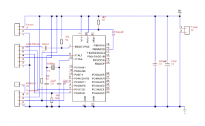
So I capture a circuit diagram:

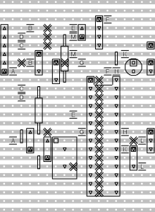
And generate a verboard layout:

The free version of VeeCAD doesn’t put component names or values on the veroboard layout, and I’ve obscured it slightly by mounting 2 of the resistors vertically (or nearly so), but you can probably figure out which bit is which if for some reason you are mad enough to want to reproduce it for yourself. Here is a zip file with the actual VeeCAD and TinyCAD data files: temp-sens-bits. I’m sure the veroboard layout could be done much better by someone who actually knew what they were doing 🙂