Categories
electronics sensors Uncategorized

Finalized currentcost interface for rPi

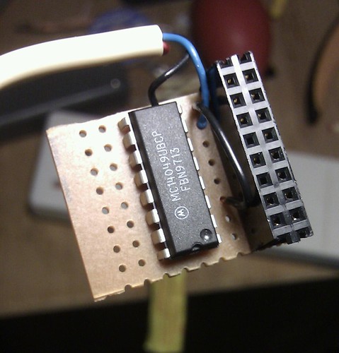
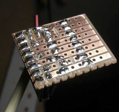
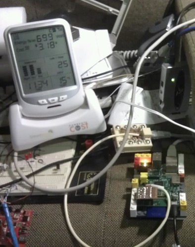
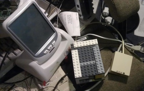
Having breadboarded it a couple of days ago, I’ve now finalized the serial interface between the Raspberry Pi and the Currentcost cc128, using some stripboard, dual header socket, CD4049, and a couple of bits of wire. Pretty straightforward; I removed a couple of pins from the header socket so I didn’t have to bridge from the outside of the socket back into the middle of the board, and made sure that all unused gates have their outputs floating and their inputs tied to something (in one case I’ve actually fed the input of a spare gate from the output fed to the rPi RX line; yes it will slightly increase the current consumption (as I’ve got an extra gate switching instead of staying static), but the effect will be tiny and it was easier than cutting the trace and fixing it all up with wires). The stripboard could have had the outer two rows of holes trimmed off but it doesn’t interfere with anything so I didn’t bother. The LEGO case has been improved now that I don’t have wires out the side (and has a transparent block near the LEDs on the rPi – works very well).

Parts
Note the two missing pins in the header. There's a missing cut on the stripboard, and one cut in the wrong place.
Top view
Top view
Bottom view
Bottom view, with missing cuts added and wrong cut bridged; yes my soldering is awful.
In situ
With cc128 meter and rj45 connection
Boxed and ready to go


Machine is now under the bed driving the (USB) bedroom speakers using shairport and feeding power data to my main server over MQTT.

5 replies on “Finalized currentcost interface for rPi”

I am Trying the same thing, Using the same cc128 I am taking serial data from pin 6 on the rj45 then feeding it through 2 gates of the 4049 and into rxd pin 10 of the PI, Using python and perl all I get is random ascii returned. Please could you confirm the serial port it ttyAMA0 also does the data need inverting

I don’t think pin6 is right. It is pin8, with pin4 as ground. See http://www.techtoniq.com/forum/viewtopic.php?f=5&t=385 – this matches my memory of using the brown and blue lines from an old ethernet cable when I was testing it.

ttyAMA0 is definitely right. No need to invert the signal. Baud rate should be 57600. The python command I’m using to open it is:

usb = serial.Serial(port=sys.argv[1], baudrate=57600, timeout=10)

(yes it isn’t a USB interface, but it was when the code was written).

Leave a Reply

Your email address will not be published. Required fields are marked *