Progress has been made.
Firstly I’ve learnt to solder TQFP surface mount packages:

And secondly I’ve used the resulting breakout widget to replace the Adafruit module on my breadboard:
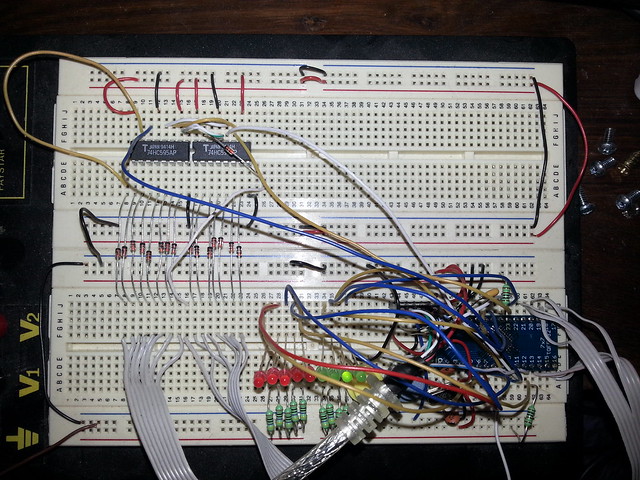
Top left you can see the pair of shift registers which drive the keyboard matrix columns through the bank of diodes and the ribbon cables at bottom left, bottom right is the soldered board from the picture above, bottom centre are the LEDs; red ones for numlock, capslock etc, green ones for debugging the state of the device. The ribbon cable off the bottom right of the board connects to the row outputs of the keyboard matrix.
Next step: design a board.
Leave a Reply